L1 is one half of the secondary winding of a center-tapped 8 ohm to 1K ohm audio transformer, coupling the output of the JFET to the input of the third stage (which consists of Q2, a 2N3904 bipolar junction transistor biased for Class-A operation by R4, R5, R6, and R7). The second stage is an inductive-capacitive network consisting of C2, C3, C5, C6, and L1. All that is necessary is to filter our signal to remove activity outside our frequency range of interest, and this is accomplished by the second stage. Although this is a radio receiver, no detection or demodulation is necessary since our desired signal is already in the range of audible sound. This allows a varying electric field on the antenna to produce a proportionally varying voltage at the output of the device. Q1 is a junction field-effect transistor (JFET), which has a very high input resistance and uses an electrostatic charge on the "gate" electrode to control current moving from source to drain through the device by varying the amount of available charge carriers. The antenna is capacitively coupled to Q1 through C1, while C9 shunts excessively high frequency signals directly to ground and also helps prevent unwanted oscillation. The receiver itself consists of three stages. McGreevy's website on VLF radio reception. The receiver design comes directly from Stephen P. The other end of the coaxial cable was terminated with a phono plug (RCA style) which plugged into the antenna jack on our receiver.

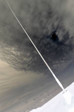
The coaxial cable was approximately half a meter long and was coiled up on the bottom of the pod so that the shielding could act as a sort of counterpoise against which to reference the signal coming in on the antenna. This wire hung vertically from the bottom of our pod and was soldered to the conductor of a coaxial cable inside the pod. The antenna consisted of a 1 meter length of very flexible insulated stranded copper wire (the type used for multimeter probes). The electrical system of our experiment consisted of four main parts: This is because the ion density of the atmosphere changes due to the earth’s position with respect to the sun during different times of the day and year. It has been shown that the best time to detect atmospherics is at night and lowest during midday and during the summer months. Atmospherics are easily detectable and propagate very well through the atmosphere between the ground and the ionosphere. They propagate along field lines across the earth to the opposite hemisphere at frequencies between 3 kHz and 30 kHz. They get their unique whistling quality when the energy from the signal travels through the ionosphere and is scattered by plasma in the magnetosphere. VLF and ELF waves are detected as whistlers or cracks because of their impulse-like shape in time. The most common frequencies found in the atmosphere are ELF (extra low frequency), VLF (very low frequency), and atmospheric noise. This radiates signals at a broad range of frequencies which propagate through the atmosphere. A major source of this noise is lightning because the current that flows through the lighting channel acts like a radio antenna. Using an appropriate receiver, these signals can be converted to an audio recording distinguishable to the human ear. The earth’s atmosphere is filled with electronic noise that can be detected at higher altitudes. The sferics per minute settled in the range of 0-8 upon landing. Beginning at the descent, the recorded data was diluted with sounds from the pod's thrashing behavior. The activity remained relatively constant for the remainder of the ascent. This suggests that a slight increase in altitude from the ground significantly enhances the ability to measure atmospheric noise. There was a significant increase in sferic activity between the balloon's liftoff and 1,230 feet, the average activity increasing to roughly 110 sferics per minute. These pulses were integrated over time, giving us measurements of sferics per minute.


The data recorded consisted of sferics, short pulses of electromagnetic radiation from lightning. The receiver was shielded by a metal casing to prevent any interference with the circuit. A vertical one meter wire was connected to the input of the receiver and protruded externally from the pod to have maximum exposure to possible VLF events. The receiver was designed to detect variations in electric field in the audio range between 150 Hz and 10 kHz.

In this experiment, the noise was recorded using a radio receiver connected to an audio recorder. Research Group: Nathan Fickert, Chris Grochowski, Jon Hoff, and Ryan RichardsonĪ radio receiver in an insulated pod was sent up in a weather balloon to record atmospheric noise, or sferics, in attempt to detect very low frequency (VLF) events.


 0 kommentar(er)
